and high-voltage electric equipment
10 Chelyabinskaya Str., Ozersk, Chelyabinsk region, 456783, Russia
Phone: (35130) 4-36-40; fax: (35130) 4-87-15; e-mail: enerprom@aopoes.ru
Sales department. Phone: (35130) 4-82-45, 4-17-79; fax: (35130) 4-46-83; e-mail: marketing@aopoes.ru
 Non-standard electric equipment up to
  Standard electric equipment up to 1000 V
 Electric equipment above 1000 V
Complete distribution devices KRU-APS(E) of the voltage 6 and 10 kV
Complete transformer substations of KTPK-E type with the capacity from 25 up to 630 kVА and voltage up to 10 kV
Front side access switchgears of KSO-203 series
Complete switchgears of K-01E series
Complete switchgears of K-01ES series
Indoor transformer substations of KTPV series of capacity from 250 up to 1000 kVА and voltage up to 10 kV
The station of commercial account of 10 (6) kV (SCA)
 Electrochemical protection
 Block-module constructions
 Metal working and services
|
Front side access switchgears of KSO-203 series
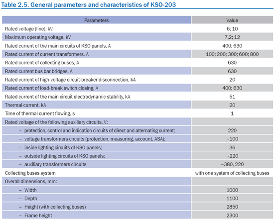
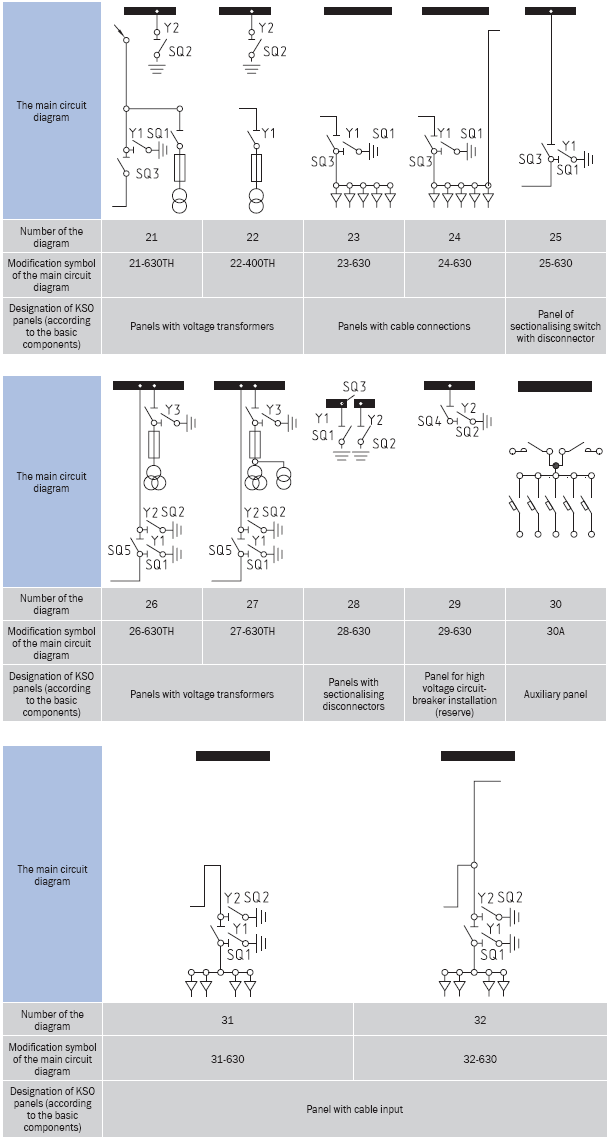
The metal housing of the panels of KSO-203 series is produced on modern hi-tech equipment and is sprayed by resisting powder epoxy paints with electrostatic method. The panel design and removable doors allow placing various equipment, and it is easy to be removed and installed or replaced with the similar equipment. Thus, there is the installation compatibility with the panels of KSO-292 and KSO-298 series. All these advantages allow to increase considerably life cycle of the product, at the same time having reduced time and expenses for its operation and service. KSO-203 panels fully comply with the requirements of state safety standards and have the certificate of conformity № РОСС RU.ME25. B01361. Operation conditionsAmbient temperature from minus 10 up to plus 40°С for climatic modification UHL3.1 is in accordance with GOST 15150-69. Altitude above sea level is no more than 1000 m. KSO-203 panels are not intended for operation in atmosphere contaminated by gases, evaporations and chemical depositions harmful to insulation, and also in explosive and fire-risk environments.
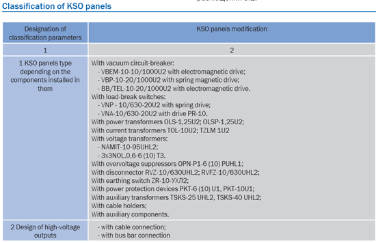
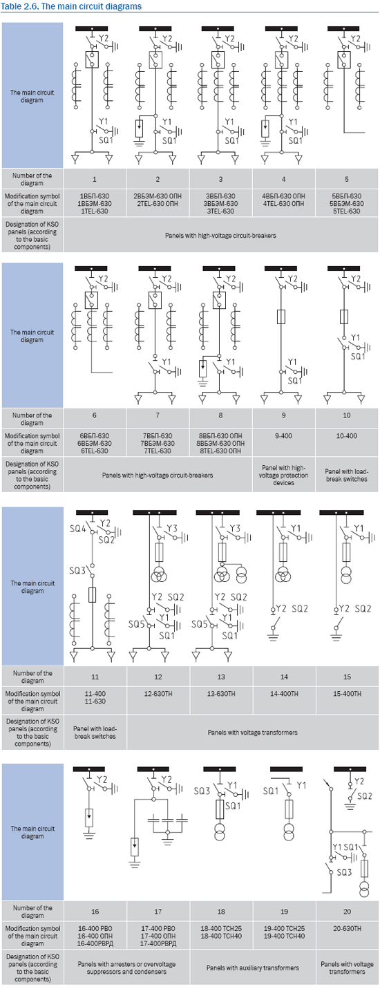
Delivery conditions Заказ камер КСО-203 осуществляется по опросному листу. По требованию заказчика возможно изготовление камер по нетиповым схемам и комплектация любым, в том числе и импортным, оборудованием. Х1 - serial number of the main circuit diagram; Х2 - symbol for high-voltage circuit-breaker (if available): VBP - the Saratov vacuum circuit-breaker with a spring magnetic drive; VBEM - the Saratov vacuum circuit-breaker with an electromagnetic drive; TЕL - the vacuum circuit-breaker with an electromagnetic drive, magnetic "lock" and telemechanics; А - automatic switching (if available); Х3 - rated current of the panel, in amperes; Х4 - designation of the basic components (if available): TSN - auxiliary transformer; TN - voltage transformer; RVO, RVD - arrester type, OPN - overvoltage suppressor. When ordering it is necessary to specify a particular modification of the main circuit diagram.
The example of KSO-203 panel symbolic notation when making an order:KSO-203-8VBEM-630 OPN-UHL3.1 - the panel of KSO-203 series with the main circuit diagram number 8, with vacuum circuit-breaker and electromagnetic drive, with the main circuit rated current 630 A, with overvoltage suppressors, climatic modification UHL, category of installation 3.1. Panels are completed with electric equipment of rated voltage 6 and 10 kV: power transformers, arresters, power protection devices, power transformers. Typical versions of KSO-203 panels are determined by a particular diagram of the main and auxiliary circuits and by rated parameters of built-in devices.
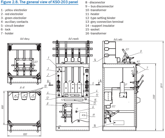
Design and actionThe panel represents a metal frame, welded of bent steel sections. Inside the panel there are two compartments with the main circuit components. On the front side there are disconnector drives and blocking buttons, connected to the vacuum circuit breaker. Indication of the circuit-breaker position is realized by indicators located on KSO-203 front side. Bus isolator is installed above the compartments. Collecting buses are placed on support insulators. Access into the circuit-breaker, voltage transformer or protection device zones of the panel is provided through the higher door. Access into the cable connections, power transformer, arresters and disconnecters zones of the panel is provided through the lower door. Between the door with the auxiliary circuits devices and the circuit-breaker the removable protective screen, preventing access into the high voltage zone, is installed. The lower door and protective screen have sight holes to watch the equipment without de-energizing. On the front side of KSO-203 panel there is a tilting yoke on which the switch and indoor lighting lamp of voltage 36V are installed. Outside there is a filament lamp of 220V for the front side of KSO-203 illumination. Exterior lighting of the panels is switched on outside KSO-203. Collecting buses and bus disconnector of KSO-203 panel have a cage on its front side. The frame of the panel is directly welded to earthed metal structures.
Auxiliary circuitsThe higher door is a plane on which the scheme of auxiliary circuits is mounted. On the front side of the door there are the devices with rear connection to wires (protection, control and indication relays, counter and microprocessor devices). The scheme of auxiliary circuits can be produced both on electromechanical relays, and on microprocessor devices (BMRZ, SIRIUS, SЕРАМ, SPAC).
ProtectionIn panels with high-voltage circuit-breakers the following kinds of protection can be applied:
InterlocksIn order to prevent erroneous operations while servicing panels, according to GOST 12.2007.4-75, the following interlocks are designed:
Note - Electromagnetic interlocks are produced at request of the consumer according to the diagrams of auxiliary circuits in KSO-203 panels. At request it is possible to install safety locks on the doors of KSO-203. In KSO-203 panels earthing switches with lockable drives can be used. There is also an auxiliary panel both detached, and with panels with auxiliary transformers. The design of KSO-203 panels provides all panels being assembled in a row for the main circuits connection by both collecting, and line buses. At two-row arrangement bus bar bridges with disconnectors and without them are used for connection by collecting buses. The design of high-voltage inputs provides both cable, and bussing connection.
|
|
skilled consultants will help you to find optimal
decision for your business!
Phone: (35130) 4-36-40; fax: (35130) 4-87-15,
e-mail: enerprom@aopoes.ru, site: www.energoprom.biz, www.enprom.ru.


